ER40 Threaded 5″ Drive Plate System

ER40 5 Inch Plate BackER40 5 Inch Plate FrontER40 Rotary Table-Indexer with Optional 5 Inch Plate in Horizontal Working PositionER40-Rotary-Table-Indexer-with-Optional-5-Inch-Plate-in-Vertical-Working-Position

Click any image for Full Size

Check out the following Video:

https://youtu.be/M-pCkBa-vls

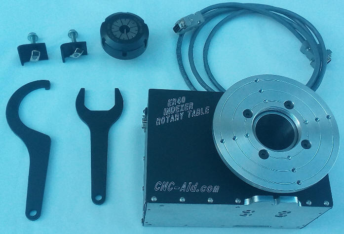
Please Note that the “ER40 Rotary Table Indexer” is Not Included

The 5″ Drive Plate System can be used as is, or modified for ANY ER40 threaded nose device of your choice.

Use it for Driving/Indexing/Fixturing, or whatever your need is.
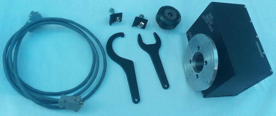
In the box:

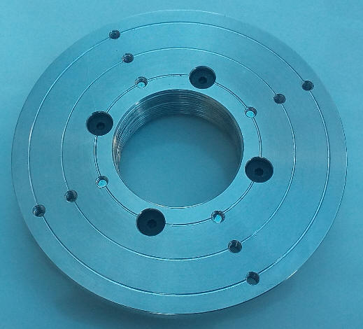
(1) ER40 Threaded 5″ Drive Plate with pre drilled and tapped holes

(1) (3″ ER40 Threaded Drive Nut with pre drilled and tapped holes

(4) #10-24 mounting screws Flat Socket Head

(4) #10-24 mounting screws Hex Head Bolts

Instructions + the 3 B/C Diameters for the (12) pre-tapped #10-24 holes on the 5″ Drive Plate are 2 ½”, 3 ½”, and 4 ½”


Made and Coming to you from Canada!

FREE Shipping to Canada and USA (Lower 48)

Contact us for anywhere else

Special $129.00 USD


Important Instructions:

The ER40 Threaded 5″ Drive Plate System can be used as is, or modified for ANY ER40 threaded nose device of your choice. You can use the existing #10-24 tapped holes and/or re-drill, re-tap, re-machine. Use it for Driving/Indexing/Fixturing, or add smaller/bigger/thinner/thicker drive plates for indexing, or whatever you like! “IMPORTANT PROCEDURE” for mounting the 5″ Plate and 3″ Clamping Nut Assembly. The ER40 nose thread has a “fairly large pitch diameter tolerance by design” resulting in tight/loose fits from any ER40 nose thread fit to the next. This is why the need for the following “IMPORTANT PROCEDURE”.First… screw on the 3″ Clamping Nut on to any ER40 spindle nose thread of your choice, then… spin on the 5″ Drive Plate until it is against the 3” Nut.  Next… unscrew the 5” Drive Plate “while holding the 3” Nut in place” until the small engraved lines between the Plate and Nut match to orient the original fit of the assembly. This will leave a ”VERY IMPORTANT GAP” between the 3” Nut and the 5” Drive Plate. Install the (4) front Flat Socket Head 10-24 x 3/8″ Clamping Screws and “then” position the assembly where you will want it to sit on the ER40 thread “before” snugging up the assembly. Again… you must maintain the “VERY IMPORTANT GAP” or you may not be able to dial and true up the “Outer Most Face” of the 5″ Drive Plate. Snug up the screws “equally” until the 5″ Drive Plate runs thru using a dial indicator on the “Outer Most Face”. You will obviously need to Power the CNC ER40 Indexer Rotary Table to rotate the 5″ Drive Plate while dialing.

DON’T OVER TIGHTEN!

NOTE: Alternately… you also have the option of using (4) Hex bolts from the rear instead to mount the 5″ Drive Plate and 3″ Clamping Nut Assembly as explained above. This might be preferred if access to the front screws are blocked by what your adding to the 5″ Drive Plate, OR… if that’s not an issue… you could use all (8) fasteners (4 front and 4 back) for a more controlled and solid setup.“IF DONE CORRECTLY”… this will prevent the Assembly from spinning on the ER40 thread when a reasonable amount of torque is applied in either direction, and will also provide a more rigid setup, and help prevent possible face distortion of the 5” Plate when using only 4 fasteners.It’s important to not over tighten the assembly or you risk stripping the threads. The large ER40 thread diameter provides plenty of anti-spinning resistance without requiring over tightening. “SNUG” is all that is required.